


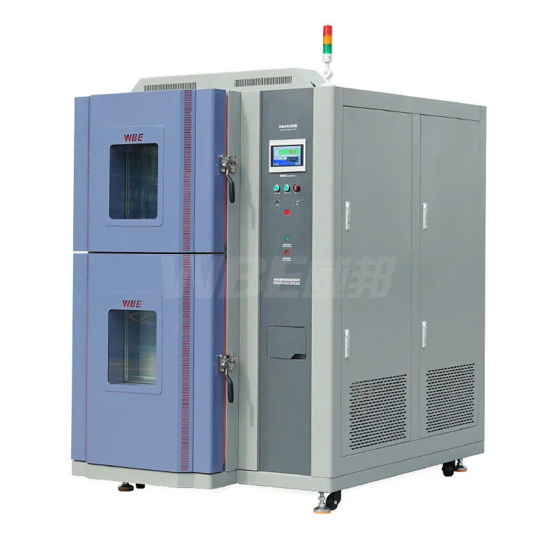
A thermal shock test chamber is not one machine. It is a family, and the structure you buy decides which failures your product can ever show you. Two-zone basket chambers move the sample between hot air and cold air. Three-zone thermal-storage chambers hold the sample completely still and switch the air around it. Liquid-bath chambers lower the sample into heated fluid and then chilled fluid. All three deliver a shock. None of them deliver the same shock.
This guide follows the order a purchase decision actually runs, not the order a catalogue lists models. We will cover five things in sequence: how the three structures differ at the level of the part itself, what the two-zone basket design buys you and what it quietly costs you, why the three-zone storage design is the one that lets you keep the sample powered, what only a liquid bath can expose, and how to choose between them by sample and by failure mode. Then we put the whole decision into a table you can carry into a review meeting.
The short version, if you only read this far
- Structure decides the thermal path the part actually feels, so it decides which failures are reachable.
- Two-zone basket types convert fastest, but the sample travels, and moving cables are a real problem.
- Three-zone storage types keep the sample still, which is exactly what makes powered, wired testing practical.
- Liquid baths move heat far faster than air and reach failures that air-to-air methods leave hidden.
Step 1: The Three Thermal Shock Test Chamber Structures and the Process Each One Delivers
Every one of these machines produces a shock, but the shock arrives by a different route, and the route is what your product actually experiences. That is the whole reason two machines with identical temperature extremes can find completely different failures, and it is why the structure deserves to be chosen before the temperature range.
| Structure | How heat reaches the part | What the part feels | What it is good at |
|---|---|---|---|
| Two-zone basket transfer | The sample is carried from an already-stabilised hot zone into an already-stabilised cold zone | A near-instant change of ambient, plus the motion of the transfer itself | The sharpest air-to-air transition in the smallest footprint |
| Three-zone thermal storage | The sample stays put; dampers open and close to route pre-heated or pre-cooled air past it | A rapid change of ambient with no movement at all | Clean thermal shock while the sample stays wired and powered |
| Liquid bath immersion | The sample is lowered into a heated bath and then a chilled bath | A steep thermal gradient driven by direct contact, not by air | Exposing rate-of-change failures that air cannot reach |
Read the middle column again. Two of the three routes add something on top of the temperature change, either motion or fluid contact. Only one route delivers almost nothing but the change itself, and that difference is what the next three steps unpack. Once you can name the route your part will travel, the rest of the decision becomes a series of concrete checks rather than a preference.
Step 2: The Two-Zone Basket Type, Fast Conversion Paid For With Handling
The two-zone basket chamber converts temperature faster than almost anything else in the same footprint, and it pays for that speed with everything that has to travel alongside the sample. Understanding the trade is the difference between choosing it deliberately and discovering it after installation.
Here is what the design does well:
- Both zones are already at temperature before the sample arrives, so the transition is close to instantaneous.
- Only two controlled zones are needed, which keeps the control logic and the machine envelope simple.
- Small parts, single components and coupons cycle quickly, so you collect more cycles per working day.
Now the part most specification sheets leave out. The sample is moved, and anything attached to it moves too:
- The transfer adds mechanical motion on top of the thermal load. If your failure mode is a solder joint, you would rather not have a mechanism pulling on it at the same moment.
- Cable routing becomes the hard problem. A power or instrumentation harness has to survive thousands of transfers, and a moving bundle can chafe, fatigue or tug on the connector.
- Live monitoring is awkward. The device under test is in motion during the very moment you most want to watch it, and a long harness across a moving basket is difficult to keep tidy.
- Heavy or bulky samples are limited by what the basket and its drive can carry safely and repeatedly.
None of this makes the design wrong. If your sample is small, unpowered and you simply need the sharpest possible air transition, the basket type is the efficient answer, and the basket type hot and cold shock test chamber is built exactly for that brief. A connector maker in Southeast Asia runs small unpowered coupons through this arrangement and gets its cycles out of the way early in the week.
But if your sample is wired and live, the moving design works against you. The next step explains why the still design wins that argument, and what it unlocks once the sample stops moving.
Step 3: Three-Zone Thermal Storage, Why the Sample Can Stay Wired and Powered
The three-zone thermal-storage design keeps the sample completely still and changes the air around it instead, and that one fact is what makes live, instrumented testing possible. There are three areas inside the machine: a hot storage zone, a cold storage zone, and a test zone. Dampers open and close to draw pre-conditioned air from storage into the test zone, so the air arriving at the sample is already at the target temperature rather than being heated or cooled on the way.
This is the principle behind the three-slot thermal shock test chamber we commission most often for electronics customers, including the WBE-LR3 three-slot thermal-storage platform. The sample never moves. The dampers do all the work. That single design choice changes four things for you:
- Your cables stay where you route them. A power lead and a thermocouple can be fixed once and left for the whole campaign, so nothing fatigues between cycles.
- You can monitor the part electrically through the whole cycle, at both extremes, not only before and after.
- You can energise the device under test and record its behaviour while it is hot and while it is cold, which is how an intermittent fault is caught rather than only an outright failure.
- No mechanical shock is superimposed on the thermal load, so a cracked joint is caused by temperature, and you can say so with a straight face.
The WBE-LR3 also runs four shock modes, and the mode you pick is a test decision rather than a menu setting:
- High to room to low: the classic three-point profile, with a defined return to ambient between the extremes.
- Low to room to high: the same cycle started from the cold end, for parts whose cold behaviour sets the risk.
- Low to high: a direct two-point transition with no ambient pause.
- Room exposure: holding the part at ambient as a defined step, used when the plan calls for a controlled return rather than a ramp.
A machine like this runs between two extremes all day, so efficiency is not a side note. WBE uses electronic expansion valve technology on the refrigeration circuit, which meters refrigerant precisely instead of over-cooling and correcting afterwards, and that cuts energy use by 45% or more. In plain terms, the compressor works less for the same profile, and a chamber that is always fighting between two setpoints is exactly where that matters.
A still sample with live monitoring tells you what the part did during the shock. There is one more structure that asks a different question entirely, and it is the one air can never answer.
Step 4: The Liquid-Bath Type, What Air-to-Air Simply Cannot Reach
A liquid bath moves heat into and out of the sample far faster than air ever can, and that is precisely why it exposes a class of failures that air-to-air methods leave hidden. The physics fits in one line: a moving liquid carries heat by direct contact, and its heat-transfer coefficient is much higher than that of air, so the surface of the part follows the setpoint almost immediately.
The result is a steep internal gradient. The outside of a package, a seal or a coating wants to expand or contract while the inside is still catching up, and the two layers pull against each other. Air cannot drive that gradient as hard, because with air the surface never moves that fast. A liquid-bath machine, such as our liquid tank thermal shock test chamber in the WBE-LR2YC immersion configuration, is chosen when the failure you are chasing is a rate-of-change failure:
- Interfacial delamination between layers of a package or a laminate, where two materials want to expand at different rates.
- Cracks in vias and solder joints driven by the rate of the change rather than by its size.
- Seal and gasket failures in parts that rely on a flexible joint to stay tight.
- Separation in stacked or bonded assemblies, where the bond line feels the gradient first.
The trade-offs are just as real. The fluid has to be compatible with your sample, the part usually has to be cleaned and dried afterwards, and live electrical monitoring inside a bath is far harder than in air. So a liquid bath is not the better machine. It is a machine that answers a different question, and it earns its place when the question is how fast the part can take the change.
You now have the three thermal routes and the failures each one can reach. The last step is to match them to your sample and to the specific failure you are trying to force.
Step 5: Choose the Right Thermal Shock Test Chamber by Sample and Failure Mode
The fastest way to get this wrong is to choose by transition seconds alone, because seconds say nothing about what the part experiences inside. Choose instead by the thermal gradient your failure mode needs and by whether you must keep the part powered. This is the table we walk through with customers in the first meeting, so find your row and then read the reason.
| Your sample and test need | The failure you are chasing | Structure that fits |
|---|---|---|
| Small unpowered coupons that need the sharpest air change | Contact and edge damage under rapid ambient change | Two-zone basket transfer |
| Powered, wired, instrumented boards | Solder joint and die-level fatigue under live bias | Three-zone thermal storage, WBE-LR3 |
| Large or heavy parts that need horizontal handling | Thermal fatigue where the fixture must not travel vertically | Horizontal two-zone type, WBE-LR2W |
| Coated, sealed or multi-layer assemblies | Delamination from a steep internal gradient | Liquid bath immersion, WBE-LR2YC |
| A mixed programme across several products | Several failure modes in one campaign | Three-zone storage with customisable zones |
Once the structure is fixed, the next layer is standards, and the same platform family is documented against the profiles most of our customers answer to. GJB 150.3 sets the high-temperature side of a defence programme, which is the limit your heating side has to hold. GJB 150.4 sets the low-temperature side, which is what your refrigeration side has to reach with the load inside. GJB 150.5 covers the temperature shock itself, and that is the document that decides whether you need a still sample or a moving one. On the civil side, GB/T 2423.1 and GB/T 2423.2 give you the cold and dry-heat methods that mirror the international approach. For packaged semiconductors, JESD22-A106B governs the thermal shock profile. MIL-STD-810G and MIL-STD-202G appear whenever a defence or aerospace programme wants its own evidence trail.
The company behind the platform matters too, because someone has to stand behind the profile you program. WBE has been building reliability test equipment since 1995 from Dongguan, Guangdong, China, in our own 12,000+ square metre plant, and we hold ISO9001, ISO14001, CE, RoHS and CNAS. Standard models leave the factory in 15 to 20 days. Start with the thermal shock test chamber range to compare the structures side by side, and note that the horizontal two-chamber thermal shock chamber exists for parts that are better handled on their side than lifted vertically.
Frequently Asked Questions
Can one machine cover two-zone, three-zone and liquid-bath behaviour?
No, and any supplier who says yes is describing three machines. The thermal path is set by the structure, so a basket chamber cannot behave like a still chamber, and neither can imitate a bath. What one platform family can share is the controller, the logging logic and the calibration routine, which makes a second structure a small project rather than a rebuild.
Which structure should we choose if we plan to power the sample?
The three-zone thermal-storage type. Because the sample never moves, a harness can be routed once and left in place, and electrical monitoring can run through the entire cycle. A basket type forces you to solve a moving cable problem on top of a thermal one, and that is usually the point where a clever plan turns into a maintenance routine.
Is a liquid bath always harsher than air?
It is faster, not simply harsher. A liquid bath drives a steeper gradient across the part, which is what certain delamination and seal failures need. If your failure mode is driven by the absolute extreme rather than by the rate of change, a faster method may tell you nothing that an air chamber could not already tell you.
Do we need all three structures in one lab?
Most labs we work with start with one and add the second later. Pick the structure that matches the failure you are chasing now, keep the fixture plate and the logging format consistent between machines, and the next structure slots into an existing habit instead of demanding a new one.
Choosing a thermal shock test chamber is really a choice about which thermal path your product will travel, and that choice is made long before anyone programs a profile. Get the structure right, keep the sample still whenever you need to watch it, and let the failure you are chasing pick the machine, never the other way round.
Match the structure to the failure you are chasing
Compare the two-zone, three-zone and liquid-bath platforms side by side, then describe your sample and the failure mode and we will point you at the structure that can actually reach it.
Compare thermal shock platforms Describe your sample and profile